Simulate a 6DoF Robotic Arm in Gazebo and ROS2
In this tutorial, you will learn how to simulate a robotic arm from scratch. We will be using a 6DoF robotic arm from Doosan Robotics. Gazebo and ROS2 are the software to perform this simulation. All the code, URDFs and configuration files can be found and downloaded in my Github Repository
-
Github Repository (LINK)

1
Outcomes after this section
-
Correct installation of ROS2 control and Gazebo packages
-
Correct configuration of your files for ROS2 (control and simulation)
-
Visualize your robotic arm in RVIZ 2
-
Simulate your robotic arm in Gazebo
-
Make your robot execute a simple trajectory
2
Prerequisites
In order to succeed with this tutorial, please make sure you have installed and ready the following points:
-
Ubuntu 20.04
-
Full installation of ROS2 Foxy
3
About the Robotic Arm
We are going to use a 6 DoF robotic arm from Doosan Robotics. Each part that makes up this robot for simulation is building using a COLLADA file (a Digital Asset Exchange file format for 3D applications) and the URDFs. Thanks to Doosan Robotics and its repository we could obtain all these files ( LINK )
We are going to simulate the A0912 robotic arm. You can have a look at this robot features here (LINK)
4 Installation Packages and Run the Simulation
Let's install the packages and run the simulation so you can see what we will get with this repository. The first thing you have to do is create your workspace, in a new terminal write:
source /opt/ros/foxy/setup.bash
mkdir -p ros2_ws/src
cd ..
colcon build
Install some dependencies and necessary packages:
sudo apt install python3-vcstool
sudo apt install ros-foxy-test-msgs
sudo apt install ros-foxy-control-toolbox
sudo apt install ros-foxy-gazebo-ros-pkgs
sudo apt install ros-foxy-xacro
sudo apt install ros-foxy-joint-state-publisher-gui
Then you need to download and build in your workspace the following packages:
-
ros2_control framework (LINK)
cd /ros2_ws
wget https://raw.githubusercontent.com/ros-controls/ros2_control/master/ros2_control/ros2_control.repos
vcs import src < ros2_control.repos
colcon build
-
gazebo_ros2_control (LINK)
cd ros2_ws/src
git clone -b foxy https://github.com/ros-simulation/gazebo_ros2_control.git
cd ..
colcon build
Make sure to install these packages FROM SOURCE, and point to the correct branch (FOXY) otherwise, some problems could appear. Now you can clone our repository in your workspace and build the whole workspace.
cd ros2_ws/src
git clone https://github.com/dvalenciar/robotic_arm_environment.git
cd ..
colcon build
Now open a new terminal and write the following lines:
cd ros2_ws
. install/setup.bash
ros2 launch my_doosan_pkg my_doosan_gazebo.launch.py
Open another new terminal and write the following lines:
cd ros2_ws
. install/setup.bash
ros2 launch my_doosan_pkg my_doosan_rviz.launch.py
If the installation was correct and you did not get any error, Gazebo will be open and you should be able to see a beautiful simulation of the robotic arm. Also, Rviz will be launched, and you can move the robot using the joint state publisher window

Note: The robot will not move in Gazebo yet because we are not using any controller; only the robot in Rviz will move. I will explain this in few paragraphs later.
5 Step by Step Configuration


Now that you have seen part of the results and the robot working, it is time to replicate the entire process from scratch, step by step, with all the necessary settings, configuration files and certain "tricks", which I have discovered over many hours of practice.
5.1 Create your ROS package
We will start creating the ROS package where you will use for your simulation. This package will contain all the code, configuration files and launchers, but first thing first, let's create a python package.
cd /ros2_ws/src/
ros2 pkg create --build-type ament_python my_doosan_pkg --dependencies rclpy
cd ..
colcon build --packages-up-to my_doosan_pkg
Now that you have created your packages, we will be creating the necessary folders that will contain the descriptions and config files.
cd my_doosan_pkg
mkdir config description launch rviz worlds
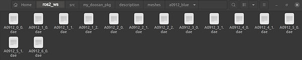
Have a look inside in your my_doosan_pkg folder you should have something like this
5.2 Add the meshes files
As I mentioned previously, we are going to use a 6 DoF robotic arm from Doosan Robotics, therefore, we need a 3D prototype (i.e. a 3D model in CAD) of each part that makes up this robot. The simulator needs these files to create a solid and realistic simulation. This tutorial will be using DAE files.
I have provided you all the DAE files (which I have previously sort and downloaded from Doonsa Robotic Repository) so you have to create a new folder called /meshes inside the /description folder and add the complete /a0912_blue folder which contains all necessary meshes files. You can obtain these files from the repository here (LINK).
5.2 Write the XACRO-URDF files
Let's make things more interesting. Now we are going to create our URDF-Xacro files. These files are extremely important because contain a tree structure telling about how to hold the robot body in terms of links and joints. Basically, these files tell the simulator how and where to locate each link and joint. Also, it is here where you import your meshes (the DAE files previously saved in the meshes folder). So, inside your /description folder you need to create a new folder called xacro. Inside that /xacro folder you have to create a file with the extension .xacro (for our case you have called this file macro.a0912.blue.xacro).
NOTE: Xacro files and URDF files are not differents; xacro is just another way of defining a URDF, not an alternative to it. The biggest difference is the use of macros making certain things easier.
Let's start by writing the first link (base) and the first joint in our xacro file. As you can see in the next image there is a tag called "mesh” inside the visual and collision tag and that is where the mesh file is added for each link. You have to do this for all the links and joints that compose your robot. This could be a very difficult and tedious job, however, the majority of the commercial robots include this description or can be auto-generated using external software. For our case, you can obtain the XACRO-URDF file complete here (LINK).
Something that I included manually in this xacro file is the damping and friction parameters (these parameters were not included in the original Doosan xacro-urdf). But after a long analysis, I discovered that these parameters help the robot to look more solid during the simulation, also prevent the robot from making strange movements, especially in the joints. The next image is an example of what could happen if you do not include the damping and friction in your description file. So make sure to try and select the correct values. See the URDF page for more details about damping and friction. (LINK).
5.3 Control plugins and configurations
Another very important thing that the original Doosan repository does not include (at least I could not find it) is the use of the necessary plugins for ros2_control and gazebo_ros2_control inside the urdf-xacro files (perhaps that is the reason why they mention the original repository does not run with the latest version of ros2_control). Therefore, I created and add this file, making this tutorial full compatible with the latest ros2_control version.
So inside the /xacro folder you create a new file and called it macro.gazebo_config_control.xacro. This file will include ros2_control tag and defines a system. We will call this file from our main xacro file (macro.a0912.blue.xacro). So let's add the ros2_control tag and the necessary configuration (command interface and possible state interfaces)for each joint.
Also, inside this file, you have to load the gazebo plugin and the configuration file of the controller. You can find the complete file here (LINK)
Note: this is one of the main differences with respect to ROS1; that is, in ROS1 the configuration yaml file was loaded in the launch file while in ROS2 it is loaded in the description URDF-xacro file.
The configuration file containing the settings of the controller. Therefore, inside the folder /config you will create a new XML file and called simple_controller.yaml.
This file is self-explanatory; it contains the type of controller and the joints to which the controller will be applied. For our case, we will be working with Joint Trajectory Controller --> Position Controller. You can find this YAML file here (LINK).
5.4 Launch files and Setup configurations
We have reached the point where we began to create our code to simulate the robotic arm in Gazebo. So we will make a launch file, which will help us start all the necessary files and packages. Inside the /launch folder, we have to create a new file; we have named this file my_doosan_gazebo_controller.launch.py
We start importing all the necessary libraries and then reading the xacro file from the share directory of the package. Then, we will be executing is robot_state_publisher, which will publish all the states of the robot to the TF and put them on the parameter server. The next step will load the gazebo world and spawn our robot. Finally, we will load and start our controllers (previously defined in the config/*.yaml file). The following image is a complete example of our launch file, but in case you need it, you can find this file here (LINK)
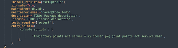
When you are working with python packages in ROS2, you need to configure the setup.py file in order to ROS find the folders and files that you just created. Therefore open your setup.py (LINK) and add the following lines within the data_files brackets:
Finally, save all these files then build the package and launch it as follow:
cd ros2_ws
colcon build --packages-up-to my_doosan_pkg
. install/setup.bash
ros2 launch my_doosan_pkg my_doosan_gazebo_controller.launch.py
If everything goes well and you do not get errors, you should receive the following response in your terminal, and Gazebo will start with our robot.
5.5 Node file for Trajectory
We have reached the final part, and probably the most interesting, of this tutorial where we will move the robot’s joint to a specific point. We will write a ROS node using an action-client to send a request to move the joints of our robotic arm. Therefore, inside the /my_doosan_pkg folder, you need to create a new python file. We have called this file joint_points_act_service.py and can be found complete here (LINK)
We have to define the correct message with the joint trajectory type, required goals, delays, and joint names for the controller to take the action
Here as well you have to add this python file in the setup.py file to be executable and ROS can run it
Finally, save all these files then re-build the package and run it in a new terminal as follow:
. install/setup.bash
ros2 run my_doosan_pkg trajectory_points_act_server
Comments?
Any questions or comments about this post will always be welcome. If you have something to say, please do not hesitate to contact me.